This manual covers in details our T-Design Distance sensor installation. T-Design Speed sensor installation is similar and should follow the same steps. Speed sensor only has 3 wires and our part is a direct replacement, with the same wire positions/configuration as OEM.
This manual does not include PDK disassembly instructions. We do not provide general PDK works support.
Your mechanic / car shop should be comfortable with disassembling / working on PDK gearbox. Common sense, independent decision making, and advanced mechanical skills is a must.
Here's helpful Rennlist thread about opening PDK:
Working with PDK and installing sensor requires advanced mechanical skills.
Do not attempt on your own if you are not comfortable with in-depth working on the car engines, gearboxes, and do not have or not comfortable with using PIWIS tool for calibration.
While installing our sensor itself is not difficult, opening PDK to get to the sensor is NOT a simple DIY. And calibration of PDK can be very frustrating and extremely challenging for unexperienced users.
We strongly recommend using a reputable car repair shop, familiar with Porsche PDK gearboxes. We can recommend shop almost in any part of the world.
Don't hesitate to contact us if have any questions about sensor installation!
Or if you have suggestions on improving these instructions.
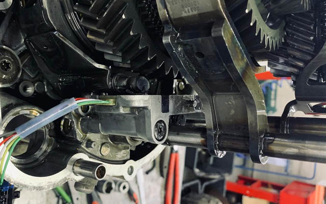
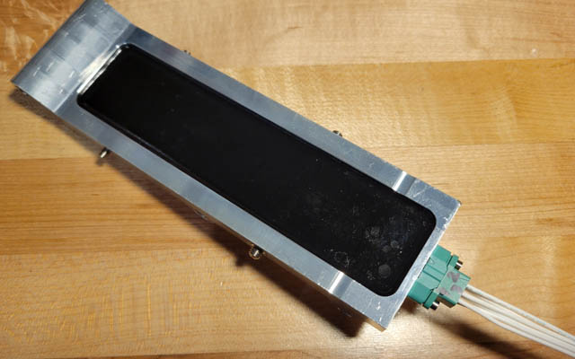
1. After gearbox is opened, take a lot of pictures of the gear position sensor, speed sensor connected to it, and the harness.
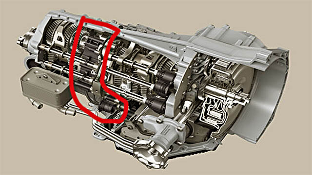
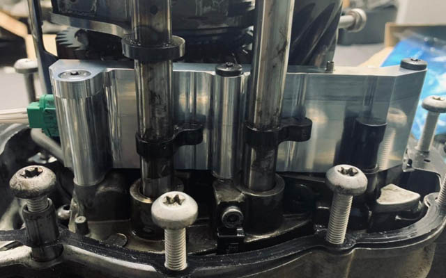
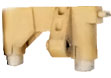
Here's the general sensor position. It can be slightly different for 911 vs Cayman/Boxster, but it's in this area of PDK gearbox.
The black round thing at the bottom of highlighted area is a plug that leads wires from oil chamber to the outside of gearbox:
2. Remove the displacement sesnor, speed sensor and the plug, by unscrewing the bolts that hold them and removing the outside connector to the plug. Plug should slide out after you remove retaining clip on the outside
3. Take the old sensor and harness out and clean the harness from oil. Don't use agressive cleaning solutions that can damage plastic on wires. Isopropyl alcohol on paper towels works well to remove oil
4. Carefuly remove the nylon zip tie near the plug. Take more pictures, so you can clearly see wire colors and positions on sensor
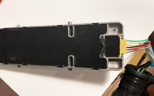
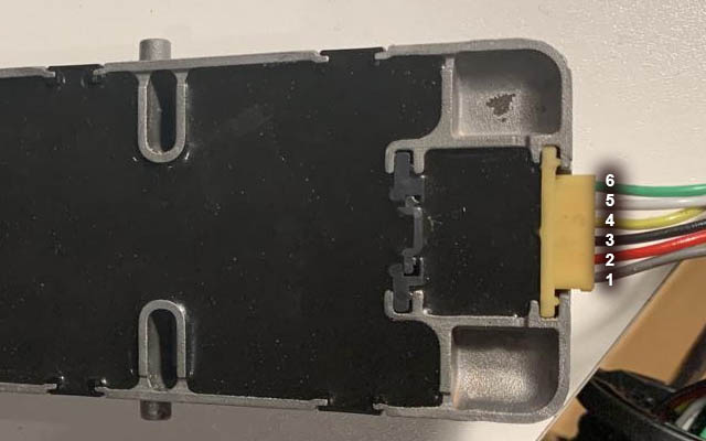
Important! From here on, all the pictures show sensor unit positioned with black/epoxy side up.
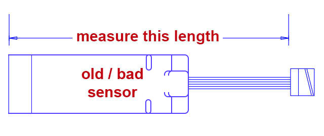
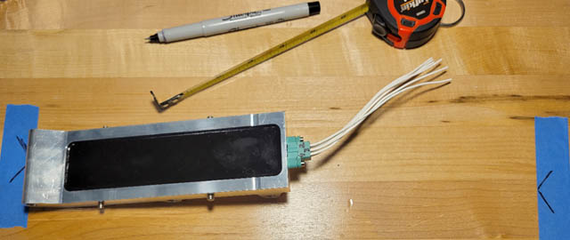
5. Measure the lenght of old sensor unit+wire to the plug. Call it L1. We will need to make new sensor + wire the same length:
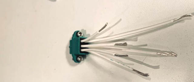
6. Mark the wires 1 to 6, using tape with good adhesion. Put labels closer to the plug and further from sensor. Make sure they attached reliably and will not get lost:
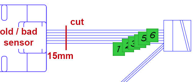
7. Cut the 6 wires leading to the *OLD* sensor, at 15 mm from sensor. Make sure your markings are securely attached and on the side of the plug. Do NOT touch/cut wires going to yellow speed sensor:
8. Put aside the old sensor. You don't need it for the rest of installaion
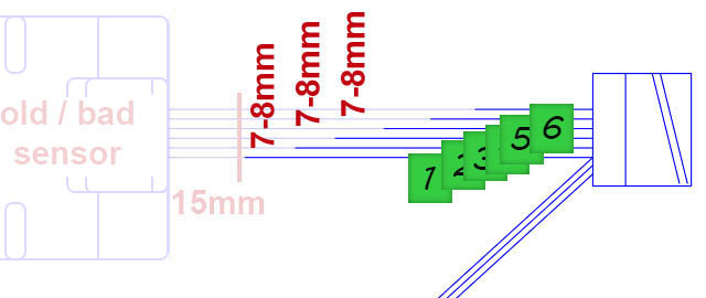
9. Cut the 6 wires leading from the plug as shown. Space cuts as shown, by 7-8mm, so they not all in same area:
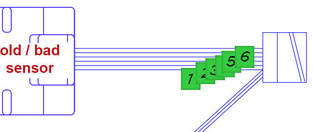
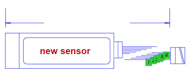
10. Take the new sensor with leading wires (green connector) attached:
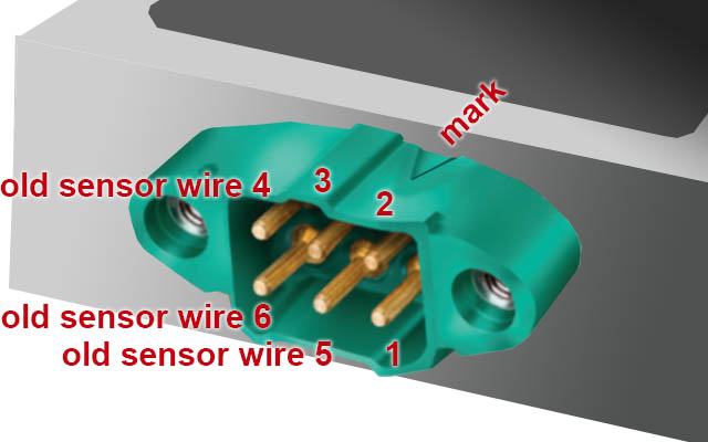
11. Use this schema to figure out where each wire from the old sensor goes. Those numbers are also marked on the green connector on new sensor
12. Mark L1 distance measured in step (5) on a solid surface (workbench/table). Place new sensor and old plug to match the distance. The idea is to get length of new sensor unit + wire same L1 as for old sensor before
Important! The new sesnor is not the same length as old. That's why you need to measure with wires
13. Mark the wires on new sensor unit to cut in the same spaced manner. Add about 10mm for connecting and twisting wires together
14. Measure everything twice. Make sure the length of new sensor+wires to the plug will be the right length after wires soldered. Better error on longer side
15. Cut the wires to new sensor as marked. Now you can detach the connector from the new sensor, so it's easier to work with:
16. Slide clear piece of provided heatshrink tubes onto each wire , far from the cut, so it doesn't get hot from soldering. You might want to slide 3 on longer ends from the new sensor, and 3 on longer ends from the plug.
Important! Provided heatshrink tubing and zip ties are designed for high temperature environment. Do not use your own tubes and ties with unknonwn specs
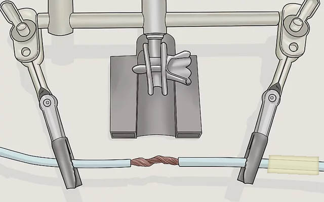
17. Strip, twist and solder the wire. Make sure solder is wicked into the connected wires, and not just outside
18. Make sure there are no sharp ends that can tear through heatshrink tubing
19. Use heatgun to shrink the heatshrink tubes. Do not use cigarette lighter on this valuable part!
20. Take a clear picture of new connections
Important! Taking pictures is important in case you will require troubleshooting/support from us
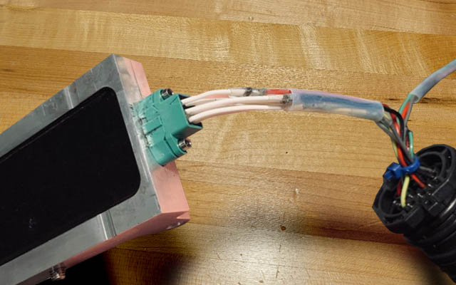
21. Tie provided zip ties in the same manner as on old sensor
22. Attach connector to sensor, so it's ready for installation into the gearbox
23. Check and clean the magnets near the sensor from any debris
24. Put everything back together into the gearbox
25. Installing gearbox back into the car
This is the end of mechanical installation
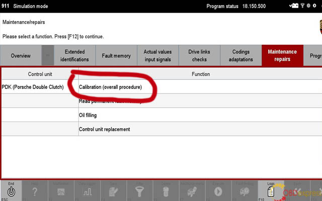
26. Use PIWIS (preferable) or AUTEL diagnostic tool to calibrate PDK
Proceed to using PIWIS tool, Maintenance Repairs section. It is often requires more than 1 attempt to finish calibration. Sometimes up to 10!
Important! Multiple sources reported calibration problems when using PIWIS III (3). We would recommend using PIWIS II (2) or PIWIS 4
Important! It always help to start with PDK bleeding procedure (Oil Filling) in PIWIS to get rid of air bubles after PDK refill. It will often resolve the calibration problems.
Select calibration procedure WITHOUT REPLACEMENT PART first. Follow prompts. See if the car runs.
If that didn't work - select calibration WITH REPLACEMENT PART and follow promts
Important! If can not complete calibration - contact us with screenshots of sensor values and cancellation condition